Distribution Board Components
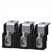
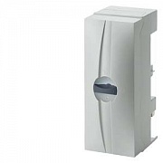
Обзор
Material properties
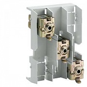
Busbar supports and busbar-mounting fuse bases (see "Built-in components") are manufactured from glass-fiber reinforced, thermoplastic polyester (color RAL 7035, light gray). The material ensures excellent mechanical, chemical and electrical properties. Furthermore, the material has an extremely low flammability and meets the requirements of UL 94 V0. This satisfies the load requirements of the busbar supports at rated operational voltage 500 V and rated currents at 200 A to 630 A, as well as the rated short-circuit strength 50 kA.
The use of busbar systems with their versatile rail-adaptable connection, switching and installation devices is an ideal and cost-effective electrotechnical enhancement of modern distribution boards due to their small footprint, compact design and quick assembly contacts. Mounting is implemented on longitudinal stays. The busbar spacing is 60 mm.
Ambient temperatures
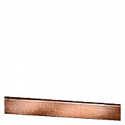
When dimensioning the busbars based on rated currents, the ambient temperature and the Cu busbar temperature must also be taken into account.
The location of the busbar system and its ability to dissipate heat through convection also play a key role in this calculation. Because conditions can vary for each distribution board, the values in the following table serve as a guideline only. However, they must be applied to the entire busbar length.
Uninterrupted currents depending on the Cu power rail dimensions and Cu busbar temperatures at 35°C ambient temperature
Cu busbar dimensions | Uninterrupted current for open busbar run - ambient temperature 35 °C | Uninterrupted current of fuse link - operational class gL/gG |
mm × mm | A | A |
12 × 5 | 200 | 200 |
12 × 10 | 360 | 315 |
15 × 5 | 250 | 250 |
15 × 10 | 447 | 400 |
20 × 5 | 320 | 315 |
20 × 10 | 520 | 500 |
25 × 5 | 400 | 400 |
25 × 10 | 580 | 500 |
30 × 5 | 447 | 400 |
30 × 10 | 630 | 630 |
As far as other types of upstream protective devices are concerned, please observe the permissible continuous current of the busbar. | ||
Dynamic rated short-circuit strength
The electrodynamic load of the busbars depends on the level of short-circuit current, the length of the busbar section through which the current flows, the support spacing of the busbar supports and, of course, on the distance between the busbars themselves. This is because, for example, if an LV HRC fuse is connected upstream to the busbars in the protective device, the let-through current iD is the maximum current to flow through this protective device. The value iD depends on the maximum system short-circuit current and the current-limiting action of the protective device used. The permissible let-through values of the protective equipment are specified by the manufacturers in the form of a current limitation diagram as a function of the so-called prospective short-circuit current (r.m.s. value of the possible rated short-circuit current for the system).
The current-limiting characteristics for the fuse links can be found in the Technical Information, see note on Technical Information at the beginning of the chapter.
For busbar supports with busbars of 12 mm x 5 mm to 20 mm x 5 mm, the distance between the holders of the support spacing should be adapted to suit the bars in the distribution board and, if possible, should not exceed 250 mm. When using busbars of 25 mm x 5 mm, 30 mm x 5 mm, 12 mm x 10 mm to 30 mm x 10 mm the distance can also be up to 500 mm. In the case of larger distances, subcarriers must be fitted, as increased support spacing reduces the dynamic stability.
It is essential to ensure that the permissible current carrying capacity of the individual busbars is not exceeded. A center infeed is required in the limit range. However, the infeed can also be carried out at both ends of the busbar.
Diagram of the dynamic short-circuit strength of the busbars
iD: Let-through values (kA) of the LV HRC fuse links, operational class gL/gG with rated current 200 A to 630 A for a prospective short-circuit current Ip = 120 kA.
Planning dimensions
Width |
| ||
NEOZED bus-mounting bases D02 | |||
Covers | 27 | 1.5 | |
Covers, extra wide | 36 | 2.0 | |
Covers, double width | 54 | 3.0 | |
DIAZED bus-mounting bases DII | |||
Covers | 42 | 2.3 | |
Covers, double width | 84 | 4.7 | |
DIAZED bus-mounting bases DIII | |||
Covers | 57 | 3.2 | |
Covers, double width | 114 | 6.3 | |
NEOZED bus-mounting switch disconnectors | 27 | 1.5 | |
Number of built-in components that can be mounted
Height | Width | Cutout width | D02/63 A 5SH5 241 | D02/63 A 5SH5 242 | D02/63 A 5SH5 243 | DII/25 A 5SH2 042 | DIII/63 A 5SH2 242 | 5SG7 230 bus-mounting switch disconnectors D02 |
mm | mm | mm | (27 mm width) | (36 mm width) | (54 mm width) | (42 mm width) | (57 mm width) | (26.8 mm width) |
300 | 250 | 216 | 8 | 6 | 4 | 5 | 3 | 8 |
500 | 466 | 17 | 12 | 8 | 11 | 8 | 17 | |
750 | 716 | 26 | 19 | 13 | 17 | 12 | 26 | |
450 | 250 | 216 | 8 | 6 | 4 | 5 | 3 | 8 |
500 | 466 | 17 | 12 | 8 | 11 | 8 | 17 | |
750 | 715 | 26 | 19 | 13 | 17 | 12 | 26 |
