Engineering the drive system
Обзор
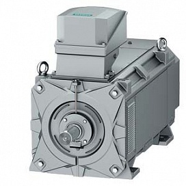
The SIMOTICS FD motor series offers scope for optimizing the drive system that comprises the frequency converter and the motor with regard to different criteria. This focuses on the following motor characteristics:
- Increased efficiency:
SIMOTICS FD motors specially designed for converter-fed operation are characterized as standard by a high degree ofefficiency – comparable to IE2 motors for mains-fed operation. For selected cooling methods (IC411 –1LM1 self-ventilated, IC416 – 1LQ1 forced-air cooled, IC71W – 1LH1 water-cooled), motors with increased efficiency are also available – comparableto IE3 motors for mains-fed operation. For motors with increased efficiency (position 7 of the Article No. = 3) in frame size 315, depending on the individual case, the thermal utilization for converter-fed operation can also comply with thermal class 130 (B) instead of thermal class 155 (F). The specified efficiencies are applicable for motor voltages in accordance with DIN EN 60034-1 N.. - Minimal noise emission for operation on SINAMICS converters:
Noise emission is minimized, especially in the range of rated speed, thanks to a perfectly matched drive system comprising a SINAMICS converter and SIMOTICS FD motor. This has been achieved on the one hand with a new electrical and mechanical design of the motor, and on the other hand using a new pulse pattern in the SINAMICS converter series that has been specially optimized for SIMOTICS FD motors. - Optimale Spannungsausnutzung:
The voltage supplied by the converter is optimally utilized. This reduces the motor current and has a positive effect on the converter either in the form of higher current reserves or lower costs for the Motor Module.
The SIMOTICS FD motors have been specially tuned to the converters of the SINAMICS G130, SINAMICS G150, SINAMICS S120, SINAMICS S150 and SINAMICS G120P series. SIMOTICS FD must be selected as the motor type during commissioning of the SINAMICS converter in the STARTER commissioning tool, or in the user interface.
The motors can also be operated with other converters under certain boundary conditions..
General information
For optimum dimensioning of the motors with regard to heating and noise emission for converter-fed operation, the following details are necessary:
- Type of infeed
- Maximum voltage available to the motor
- Converter pulse frequency, if applicable
- Required rated speed
- Required rated output, cooling method and degree of protection of the motor (selection tables)
The insulation system of the motors corresponds to thermal class 180 (H). The motors are utilized in accordance with thermal class 155 (F) as standard. For utilization of the motors in accordance with thermal class 130 (B), the output must be reduced by 14 % (derating factor 0.86).
Voltage supply via the converter
To select a catalog version of the SIMOTICS FD motor series specifically designed for converter-fed operation, the voltage available to the motor must be known. The line voltage and the configuration of the converter at the line side (infeed, rectifier or line-side converter – referred to below as the infeed) are important here.

Drive system
Unregulated infeed
If the infeed involves a line-commutated converter (unregulated infeed), i.e. a thyristor or diode rectifier (in some cases also an IGBT module), the maximum available motor voltage is lower than the line voltage. The DC link voltage and, therefore, also the output voltage of the converter is not normally regulated and changes as soon as fluctuations in line voltage occur.
The SINAMICS converter series comprises two different variants of unregulated infeed:
- Basic Infeed – SINAMICS G130, SINAMICS G150,SINAMICS S120 Basic Line Module (BLM, SINAMICS G120P):
- Line-commutated converters
- Suitable for infeed operation (two-quadrant operation)
- Power semiconductors: thyristors/diodes
- Line harmonics: total harmonic distortion factor of the line current THD(I) up to 45 %
- Low voltage load on motor winding
- Low price, compact size
- Smart Infeed – SINAMICS S120 Smart Line Modules (SLM):
- Line-commutated converters
- Suitable for operation in infeed and regenerative feedback mode (four-quadrant operation)
- Power semiconductors: IGBT modules
- Line harmonics: total harmonic distortion factor of the line current THD(I) up to 45 %
- Low voltage load on motor winding
- Medium price, medium size
The maximum voltage supplied to the motor by the converter in the case of SINAMICS converters (with optimized pulse pattern) is:
UMotor max = 0.97 · Uline
With converters of the SINAMICS G130 and SINAMICS G150 series, SINAMICS S120 Basic Line Modules, SINAMICS S120 Smart Line Modules and SINAMICS G120P, it is ensured at full line voltage (position 12 of the Article No.) that the rated motor voltages specified in this catalog are available.
If an alternative converter is to be used, it must be established in the context of project engineering that the rated motor voltage can be provided by the converter. Otherwise, the motor current rises and there is a risk of excessive motor temperature which reduces the service life..
Regulated infeed
If the infeed involves a self-commutated converter (regulated infeed), the maximum available motor voltage is higher than the line voltage. The DC link voltage and, therefore, also the output voltage of the converter is normally regulated so it is independent of any fluctuations in line voltage.
For converters of the SINAMICS S150 series that are equipped with an Active Line Module as well as SINAMICS S120 with Active Line Modules, the following applies::
- Self-commutated converter
- Suitable for operation in infeed and regenerative feedback mode (four-quadrant operation)
- Power semiconductors: IGBT modules
- Line harmonics: total harmonic distortion factor of the linecurrent THD(I) up to 3 %
- With reference to the supply network, with factory settings cosφ = 1
- Higher voltage load on the motor winding than for unregulated infeed
The maximum voltage supplied to the motor by the converter in the case of SINAMICS converters (with optimized pulse pattern) is:
UMotor max = 1,11 · UNetz
With converters of the SINAMICS S120 series with Active Line Modules and SINAMICS S150, it is ensured that the rated motor voltages specified in this catalog are available.
If an alternative converter is to be used, it must be established in the context of project engineering that the rated motor voltage can be provided by the converter. Otherwise, the motor current rises and there is a risk of excessive motor temperature which reduces the service life..
Engineering the drive system
A motor should be selected (according to voltage, speed and torque) following engineering of the drive system to ensure that all the potentials that arise from the motor and converter combination can be exploited. The motors of the SIMOTICS FD series are specifically matched to the SINAMICS converter series. This results in additional system advantages, such as reduced noise emission.
In contrast to simple selection of a motor, drive system engineering takes into account that the converter also contributes towards loading of the motor winding due to non-sinusoidal voltage and current.
In this catalog, SIMOTICS FD motors specially designed for converter-fed operation are offered for the following line voltages:
- 400 V, 50 Hz Hz
- 500 V, 50 Hz Hz
- 690 V, 50 Hz Hz
- 460 V, 60 Hz Hz
- 575 V, 60 Hz Hz
Motors for other line voltages can be supplied on request.
Depending on the type of infeed, it is possible to choose between motors whose rated voltages either lie below the line voltage (unregulated infeed) or above the line voltage (regulated infeed). Depending on which information is available for the drive system to be engineered, engineering can be performed in accordance with one of the two subsequent detail levels.
Options for engineering the drive system
Detail level 1 | Detail level 2 |
|---|---|
Simple motor selection – details of the converter are not known | Engineering the drive system – details of the converter are known – certain properties of the drive system can be optimized |
Engineering goal | |
|
|
Preconditions | |
|
|
Engineering tasks | |
|
|
Advantages of the drive system | |
|
|
Constraints with unknown converter | |
|
|
Simple motor selection – detail level 1
A motor can also be selected without precise knowledge of the converter. In this case, the motor is the central focus of the engineering and not the drive system and its optimization. Simple motor selection focuses on the large majority of applications for which an unregulated infeed is sufficient and the functions of a regulated infeed (e.g. four-quadrant operation or low line harmonics) are not required. Applications in which an unregulated infeed is normally sufficient include excavators, conveyor drives, bow thrusters, wood chippers, centrifugal pumps, fans, mills, propellers, pumps or shredders. Even in applications with a quadratic torque characteristic, regulated infeed is not normally required.
For engineering at detail level 1, the line voltage must be known.

Drive system – simple motor selection (detail level 1)
When selecting a SIMOTICS FD motor from the catalog, it is important to note:
- For all line voltages, the versions for unregulated infeed are required.
- The converter must be able to provide the rated voltage of the motor. Otherwise, the motor current rises and there is a risk of excessive motor temperature which reduces the service life of the motor.
- Due to the unknown infeed and modulation technique of the converter, the rated output specified in the catalog must be reduced (reduction factor 0.85).
- The maximum A-weighted sound pressure levels specified in the catalog cannot be used, because the modulation technique of the converter is unknown.
Engineering the drive system – detail level 2
Engineering at detail level 2 involves, in addition to the motor selection, engineering of an optimized drive system due to knowledge of the converter – especially the infeed – with regard to:
- Noise emission (for operation on SINAMICS converter)
- Voltage utilization and therefore motor or converter current consumption
- Output and torque or frame size

Drive system – engineering of the drive system at detail level 2
For engineering at detail level 2, the following must be known:
- Line voltage and, where applicable, line frequency
- Unregulated or regulated infeed
- Rated pulse frequency of the converter
When selecting a SIMOTICS FD motor from the catalog, it is important to note:
- For each combination of line voltage and infeed, a SIMOTICS FD motor can be selected that optimally utilizes the available converter output voltage.
- For operation on SINAMICS converter (firmware 4.6), operation is already possible from the rated pulse frequency fPulse = 1.25 kHz upwards without derating.
- If the converter is not a SINAMICS G130, SINAMICS G150, SINAMICS S120, SINAMICS S150 or SINAMICS G120P, the pulse frequency must be at least 2.5 kHz, otherwise the risk of excessive motor temperature rise and noise emission prevails.
- The maximum A-weighted sound pressure levels specified are applicable for operation on SINAMICS G130, SINAMICS G150, SINAMICS S120, SINAMICS S150 or SINAMICS G120P converters.
Rated motor voltages according to line voltage and infeed
Line voltage Uine | 400 V | 460 V | 500 V | 575 V | 690 V | |||||
Line frequency fline | 50 Hz | 60 Hz | 50 Hz | 60 Hz | 50 Hz | |||||
Line voltage – position 12 of Article No. | 1 | 5 | 2 | 6 | 3 | |||||
Infeed | Unregulated | Regulated | Unregulated | Regulated | Unregulated | Regulated | Unregulated | Regulated | Unregulated | Regulated |
System description – position 6 of Article No. | 2; 4 | 1; 3 | 2; 4 | 1; 3 | 2; 4 | 1; 3 | 2; 4 | 1; 3 | 2; 4 | 1; 3 |
Rated motor voltage Urated | 380 V | 425 V | 440 V | 480 V | 480 V | 520 V | 550 V | 610 V | 660 V | 730 V |
Insulation system | IIC C 500 | IIC C 690 | ||||||||
When the motor is selected correctly, it operates with optimized pulse patterns from approximately 87 % of the rated speed upwards.
If operation with space-vector modulation is planned, the converter pulse frequency (also in the case of SINAMICS converters) must be at least 2.5 kHz or the motor output must be reduced (see the following section for derating factors).
SIMOTICS FD motor on SINAMICS converter
The SIMOTICS FD motors are designed for operation with optimized pulse patterns. The optimized pulse patterns for SIMOTICS FD are only implemented when
- the motor type is selected as "SIMOTICS FD" on commissioning (SINAMICS parameter p300),
- the motor is operated with optimized pulse patterns (SINAMICS parameter p1802 = 19). With SINAMICS G converters, parameters are assigned automatically when the motor type is selected, and with SINAMICS S converters, they are assigned manually.
- Note: with SINAMICS S converters, space-vector modulation is preset and can be changed manually depending on the application to optimized pulse patterns for SIMOTICS FD. For certain applications (e.g. multi-axis drives), it is not admissible for SINAMICS S converters to be operated with optimized pulse patterns.
The thermal torque limit characteristic takes into account the transition from space-vector modulation at speeds significantly below the rated speed with optimized pulse patterns at speeds of approx. 87 % of the rated speed upwards (see diagram below).
For motors with a rated speed of 3600 rpm and a supply frequency of around 120 Hz, it must be noted that the rated pulse frequency of the converter has to be increased to 2.5 kHz. This can result in derating of the converter.
If the application requires that the converter is operated with optimized pulse patterns for SIMOTICS FD motors for speeds above approx. 87 % of the rated speed with space-vector modulation, the rated motor output must be reduced as follows in accordance with the rated pulse frequency of the converter:
- Space-vector modulation with rated pulse frequency of 1.25 kHz: derating factor 0.85
- Space-vector modulation with rated pulse frequency of 2 kHz: derating factor 0.95
- Space-vector modulation with rated pulse frequency of 2.5 kHz: derating factor 1

Modulation techniques and thermal torque limit

Selection of SIMOTICS FD in the STARTER commissioning tool
SIMOTICS FD motor on alternative converters
If a SIMOTICS FD motor is operated on an alternative converter that does not belong to the SINAMICS series G130, G150, S120, S150 or G120P, it is important to note the following:
- The selection and ordering data with the exception of the A-weighted sound pressure level for operation on a SINAMICS converter also applies to operation on an alternative converter when the rated motor voltage is available and the rated pulse frequency of the converter is at least 2.5 kHz.
- The A-weighted sound pressure levels specified for operation on a SINAMICS converter do not apply for operation on an alternative converter due to the unknown modulation technique.
- A distinction is made between the standard version (position 5 of Article No. = 4 for series 1.M1, 1.L1, 1.P1, 1.Q1, 1.H1 and 1.N1) and the increased output version (position 5 of Article No. = 5 for series 1.P1 and 1.Q1).
- A distinction is made between regulated infeed (position 6 of Article No. = 3) and unregulated infeed (position 6 of Article No. = 4).
Catalog versions and special versions
Catalog versions
Rated motor speeds
To select a catalog version, in addition to the available voltage (see section "Voltage supply") the required motor speed must also be known. The rated speeds of the catalog versions are assigned to the line supplies listed in this section in accordance with the line frequency. For the line voltages 400 V, 500 V and 690 V, catalog versions are available with the rated speeds
- 750 rpm
- 1000 rpm
- 1500 rpm
- 3000 rpm
For the line voltages 460 V and 575 V, catalog versions are available with the rated speeds
- 900 rpm
- 1200 rpm
- 1800 rpm
- 3600 rpm
Due to the converter supply, the rated motor speed does not depend on the line frequency. The rated speeds of 750 rpm to 1200 rpm are covered by the 6-pole version and the rated speeds of 1500 rpm to 3600 rpm are covered by the 4-pole version. If other rated motor speeds are required, it can be clarified on request whether it is necessary for the windings to be modified.
Recommended SINAMICS converters
In the catalog, a suitable converter of the SINAMICS series is assigned to every motor of the SIMOTICS FD series that is specially designed for converter-fed operation. This assignment is a recommendation. If the complete drive system is to be ordered, engineering of the drive system is required in accordance with detail level 2.
Converter assignment is based on the following assumptions:
- The rated motor current corresponds to the reduced base-load current IL of the converter for the standard load cycle "Minimal overloading of the converter" (see diagram below). The current IL ist is slightly less than the rated output current of the converter (by approx. 3 to 6 %).
- The line voltage assumed on motor selection is available to the converter.
- For converters with unregulated infeed, cabinet units of the SINAMICS G120P or SINAMICS G150 series are recommended.
- For converters with unregulated infeed, it is assumed that no special requirements exist (e.g.: line harmonics) and infeed operation will be used exclusively (no regenerative feedback– two-quadrant operation).
- For converters with regulated infeed, cabinet units of the SINAMICS S150 series are recommended.
- When converters of the SINAMICS series are recommended, chassis units can also be used as an alternative.
For the reduced base-load current IL of the overall converter, the following applies in the case of parallel connection of two power units:
- For connection in parallel, the SINAMICS S150 should be replaced with SINAMICS S120 CM. For SINAMICS S120 CM in the version with parallel connection of motor modules, the reduced base-load current IL for the single device is doubledand the total current is reduced by 5 %.

Definition of the standard load cycle "Minimal overloading of the converter“
Due to the numerous assumptions on which the assignment of converters of the SINAMICS series is based, it must be ensured that the assumptions quoted actually apply for the planned application when the drive system is engineered. This must apply for every point, otherwise the recommendation is invalid, especially:
- When the motor is to be operated with short-time or periodic overloading, and currents higher than the rated motor current are necessary. Note: not all rated motor currents fully utilize the reduced base-load current of the converter, which is why the recommended converter may already have current reserves. For evaluating existing current reserves, the rated motor current can be compared to the respective reduced base-load current of the converter (see table below).
- When operation with space-vector modulation is planned, the converter is not operated with the optimized pulse patterns for SIMOTICS FD motors. In this case, the pulse frequency of the converter must be at least 2.5 kHz or the output must be reduced.
- Furthermore, with unregulated infeed and operation exclusively in space-vector modulation, the motor only has a maximum voltage available to it of
UMotor max. = 0.92 · Uline
Reduced base-load currents IL of the SINAMICS converters (SINAMICS G120P, SINAMICS G150 and SINAMICS G130 or SINAMICS S150 and SINAMICS S120 technically comparable) – for engineering purposes, IL can be regarded as equal to the motor current
Output | Number of motor modules | IL | fP | Type | Number of motor modules | IL | fP | Type | Number of motor modules | IL | fP | Type |
kW | A | kHz | A | kHz | A | kHz | ||||||
SINAMICS G120P, SINAMICS G150 converters – unregulated infeed | ||||||||||||
Urated, Motor, min/Urated, Motor, max: 380/480 V | Urated, Motor, min/Urated, Motor, max: 500/600 V | Urated, Motor, min/Urated, Motor, max: 660/690 V | ||||||||||
75 | – | – | 1 | 80 | 1.25 | 1SL3710-1GH28-5AA3 | ||||||
90 | – | – | 1 | 95 | 1.25 | 1SL3710-1GH31-0AA3 | ||||||
110 | 1 | 200 | 2 | 6SL3710-1PE32-1AA0 | 1 | 171 | 1.25 | 6SL3710-1GF31-8AA3 | 1 | 115 | 1.25 | 1SL3710-1GH31-2AA3 |
132 | 1 | 240 | 2 | 6SL3710-1PE32-5AA0 | 1 | 208 | 1.25 | 6SL3710-1GF32-2AA3 | 1 | 142 | 1.25 | 1SL3710-1GH31-5AA3 |
160 | 1 | 290 | 2 | 6SL3710-1PE33-0AA0 | 1 | 250 | 1.25 | 6SL3710-1GF32-6AA3 | 1 | 171 | 1.25 | 1SL3710-1GH31-8AA3 |
200 | 1 | 360 | 2 | 6SL3710-1PE33-7AA0 | 1 | 320 | 1.25 | 6SL3710-1GF33-3AA3 | 1 | 208 | 1.25 | 1SL3710-1GH32-2AA3 |
250 | 1 | 450 | 2 | 6SL3710-1PE34-6AA0 | 1 | 400 | 1.25 | 6SL3710-1GF34-1AA3 | 1 | 250 | 1.25 | 1SL3710-1GH32-6AA3 |
315 | 1 | 570 | 1.25 | 6SL3710-1PE35-8AA0 | 1 | 452 | 1.25 | 6SL3710-1GF34-7AA3 | 1 | 320 | 1.25 | 1SL3710-1GH33-3AA3 |
355 | – | 640 | 2 | 6SL3710-1PE36-6AA0 | – | – | ||||||
400 | 1 | 710 | 1.25 | 6SL3710-1PE37-4AA0 | 1 | 560 | 1.25 | 6SL3710-1GF35-8AA3 | 1 | 400 | 1.25 | 1SL3710-1GH34-1AA3 |
450 | 1 | 820 | 1.25 | 6SL3710-1GE38-4AA3 | – | 1 | 452 | 1.25 | 1SL3710-1GH34-7AA3 | |||
500 | – | 1 | 710 | 1.25 | 6SL3710-1GF37-4AA3 | – | ||||||
560 | 1 | 960 | 1.25 | 6SL3710-1GE41-0AA3 | 1 | 790 | 1.25 | 6SL3710-1GF38-1AA3 | 1 | 560 | 1.25 | 1SL3710-1GH35-8AA3 |
630 | 2 | 1092 | 1.25 | 6SL3710-2GE41-1AA3 | 2 | 836 | 1.25 | 6SL3710-2GF38-6AA3 | – | |||
710 | 2 | 1340 | 1.25 | 6SL3710-2GE41-4AA3 | 2 | 1036 | 1.25 | 6SL3710-2GF41-1AA3 | 1 | 710 | 1.25 | 1SL3710-1GH37-4AA3 |
800 | – | – | 1 | 790 | 1.25 | 1SL3710-1GH38-1AA3 | ||||||
900 | 2 | 1516 | 1.25 | 6SL3710-2GE41-6AA3 | – | – | ||||||
1000 | – | 2 | 1314 | 1.25 | 6SL3710-2GF41-4AA3 | 2 | 1036 | 1.25 | 6SL3710-2GH41-1AA3 | |||
1120 | – | – | – | |||||||||
1200 | – | – | – | |||||||||
SINAMICS G120P, SINAMICS G150 converters – regulated infeed | ||||||||||||
Urated, Motor, min/Urated, Motor, max: 380/480 V | Urated, Motor, min/Urated, Motor, max: 500/730 V | |||||||||||
75 | – | 1 | 80 | 1.25 | 6SL3710-7LG28-5AA3 | |||||||
90 | – | 1 | 95 | 1.25 | 6SL3710-7LG31-0AA3 | |||||||
110 | 1 | 205 | 2 | 6SL3710-7LE32-1AA3 | 1 | 115 | 1.25 | 6SL3710-7LG31-2AA3 | ||||
132 | 1 | 250 | 2 | 6SL3710-7LE32-6AA3 | 1 | 142 | 1.25 | 6SL3710-7LG31-5AA3 | ||||
160 | 1 | 302 | 2 | 6SL3710-7LE33-1AA3 | 1 | 170 | 1.25 | 6SL3710-7LG31-8AA3 | ||||
200 | 1 | 370 | 2 | 6SL3710-7LE33-8AA3 | 1 | 208 | 1.25 | 6SL3710-7LG32-2AA3 | ||||
250 | 1 | 477 | 2 | 6SL3710-7LE35-0AA3 | 1 | 250 | 1.25 | 6SL3710-7LG32-6AA3 | ||||
315 | 1 | 590 | 1.25 | 6SL3710-7LE36-1AA3 | 1 | 320 | 1.25 | 6SL3710-7LG33-3AA3 | ||||
355 | – | – | ||||||||||
400 | 1 | 725 | 1.25 | 6SL3710-7LE37-5AA3 | 1 | 400 | 1.25 | 6SL3710-7LG34-1AA3 | ||||
450 | 1 | 820 | 1.25 | 6SL3710-7LE38-4AA3 | 1 | 452 | 1.25 | 6SL3710-7LG34-7AA3 | ||||
500 | – | – | ||||||||||
560 | 960 | 1.25 | 6SL3710-7LE41-0AA3 | 1 | 560 | 1.25 | 6SL3710-7LG35-8AA3 | |||||
630 | – | – | ||||||||||
710 | 1 | 1230 | 1.25 | 6SL3710-7LE41-2AA3 | 1 | 710 | 1.25 | 6SL3710-7LG37-4AA3 | ||||
800 | 1 | 1370 | 1.25 | 6SL3710-7LE41-4AA3 | 1 | 790 | 1.25 | 6SL3710-7LG38-1AA3 | ||||
900 | – | 1 | 880 | 1.25 | 6SL3710-7LG38-8AA3 | |||||||
1000 | – | 1 | 1000 | 1.25 | 6SL3710-7LG41-0AA3 | |||||||
1120 | – | – | ||||||||||
1200 | – | 1 | 1230 | 1.25 | 6SL3710-7LG41-3AA3 | |||||||
More information about SINAMICS converters can be found in the SINAMICS Engineering Manual.
Special versions
Modified windings – Special versions for non-standard voltage or speed
For versions of the SIMOTICS FD series that are not listed in the catalog, individual inquiries regarding winding modification are necessary. A winding modification may be required for:
1. A combination of defined supply and rated speed codes that are not listed in the catalog.
2. Non-standard supply systems for which a code has not been defined.
3. Non-standard rated speeds for which a code has not been defined.
Case 1 can be described with the Article No. without an additional order code. For case 2 and case 3, the appropriate order codes and plain text details are required.
- Non-standard line voltage (position 12 of Article No.: 9): Order code M1Y and non-standard line voltage and/or rated motor voltage specified in plain text
- Non-standard rated speed (position 13 of Article No.: 9): Order code N1Y and non-standard rated speed specified in plain text
Non-standard motor and load data possible on request.
Noise emission for operation on SINAMICS converter
The variants of the SIMOTICS FD motor series that can be selected in the catalog have been designed such that the maximum A-weighted sound pressure levels listed in the tables below are not exceeded in no-load operation at the rated operating point when connected to a SINAMICS converter.
This has been achieved thanks to the following measures:
- Optimized electrical design: reduced, electromagnetic noise generation
- Optimized mechanical design: improved radiation characteristics
- The choice of rated voltages, whereby the maximum converter output voltages supplied are optimally utilized
- Operation of the SINAMICS converter with an optimized pulse pattern: reduced electromagnetically generated noise, especially in the range of the rated speed ("rated range" in the diagrams below).
- Choice of suitable built-in fan (for 1LM1 and 1LL1): limiting of the aerodynamic noise
- Dimensioning of new separately driven fan: limiting of the noise from the separately driven fan
Motors of the SIMOTICS FD series can be selected in the "STARTER commissioning tool" software and in the Advanced Operation Panel (AOP) as a motor type. This ensures that operation using the named modulation technique is assured for all SIMOTICS FD motors in the respective range close to the rated speed.
A-weighted sound pressure levels under no-load operation on SINAMICS converter at rated speed (tolerance +3 dB)
SIMOTICS FD series | LPA in dB(A) |
1LM1, 1LL1, 1LN1 | 79 |
1LQ1, 1LP1 (position 5 of Article No. = 2) | 79 |
1LH1 | 78 |
For engineering a noise-optimized system, it is therefore important to:
- Select a motor with a rated voltage that matches the line voltage and the infeed of the SINAMICS converter.
- Select a motor with a rated speed that is lower than or equal to the speed(s) to be expected during operation.
- Upgrade the hardware and software of the SINAMICS converter if an existing SINAMICS converter (position 16 of the SINAMICS Article No. 0, 1 or 2) is to be used.

Schematic diagram of sound pressure level (1LM1, 1LL1)

Schematic diagram of sound pressure level (1LP1, 1LQ1, 1LH1, 1LN1)
The noise emission was able to be reduced in particular close to the rated speed (rated range). If a constant torque drive (mainly 1LP1, 1LQ1, 1LH1 and 1LN1) is implemented for low noise generation, it must be ensured during engineering that the lower operating speeds remain within the rated range. This can be achieved, for example, through the correct choice of rated speed. In self-ventilated motors (1LM1, 1LL1), the aerodynamic noise generated by the built-in fan dominates with increasing speed above the rated range. For drives of this type, the high operating speeds must be close to the rated speed.
EMC
The system comprising SIMOTICS FD in combination with SINAMICS has been checked according to the guidelines for electromagnetic compatibility 2004/108/EC and the regulations of the EMC directives. System compatibility is only provided with EMC-compliant grounding and if shielded power cables are used whose shield is conductively bonded over a large area to the metal motor terminal box.