SINAMICS S120 Chassis Format Units
Обзор
With its separate power unit and control module (Control Unit), the SINAMICS S120 drive system can be perfectly adapted to a wide variety of different drive tasks.
The control module is selected according to the number of drives to be controlled and the required performance level, while the power unit must be rated to meet requirements regarding regenerative feedback capability or energy exchange. The connection between the Control Unit and power unit is made very simply using the digital system interface DRIVE-CLiQ.
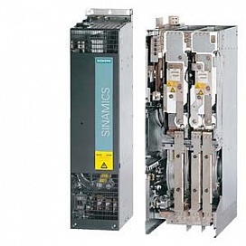
The following drive units are available in the chassis format:
- Power Modules
- Basic Line Modules
- Smart Line Modules (only available in the air-cooled version)
- Active Line Modules
- Active Interface Modules (only available in the air-cooled version)
- Motor Modules
Power Modules
The simplest variant of a SINAMICS S120 drive system comprises a CU310 Control Unit and a Power Module. In Power Modules specifically designed for single drives without regenerative feedback into the line supply, the line-side infeed and the motor-side power unit are combined in one unit.
Generated energy produced during braking is converted to heat via braking resistors.
The Control Unit is plugged onto the Power Module; in addition to the complete control intelligence, the Control Unit also has all the drive interfaces for communication with higher-level systems and interfacing of add-on components.
Line Modules
Line Modules contain the central line infeed for the DC link. Various Line Modules can be selected to address the various application profiles:
- Basic Line Modules
- Smart Line Modules
- Active Line Modules
Basic Line Modules
Basic Line Modules are designed only for infeed operation, i.e. they are not capable of recovering energy to the mains supply. If regenerative energy is produced, e.g. when drives brake, it must be converted to heat by means of a Braking Module and a braking resistor.
A line filter can be optionally installed in order to maintain the limit values according to EN 61800-3, Class C2.
Smart Line Modules
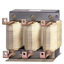
Smart Line Modules can supply energy and recover energy to the mains supply. Braking Module and braking resistor are only required, if, also for a power failure – without energy recovery option – it is necessary to brake the drives in a controlled fashion. When a Smart Line Module is used as the infeed, the matching line reactor must be installed.
Active Line Modules
Active Line Modules can supply energy and return regenerative energy to the supply system. Braking Module and braking resistor are only required, if, also for a power failure – without energy recovery option – it is necessary to brake the drives in a controlled fashion.
Contrary to the Basic Line Modules and Smart Line Modules, Active Line Modules generate a controlled DC voltage. This is kept constant, independent of any line voltage fluctuations, assuming that the line voltage fluctuates within the permitted tolerances. Active Line Modules draw a virtually sinusoidal current from the supply which limits any harmful harmonics. All the components required to operate an Active Line Module are integrated in the Active Interface Module.
Motor Modules
A voltage DC link and an inverter for supplying a motor are integrated in the Motor Module.
Motor Modules are designed for multi-axis drive systems and are controlled by either a CU320-2 or a SIMOTION D Control Unit. Motor Modules are interconnected through a common DC bus.
One or several Motor Modules are supplied with energy for the motors via the DC link. Both synchronous and induction motors can be operated.
Since the Motor Modules share the same DC link, they can exchange energy with one another, i.e. if one Motor Module operating in generator mode produces energy, the energy can be used by another Motor Module operating in motor mode. The DC link is supplied with line supply voltage by a Line Module.
Control Units
The control intelligence for all the drive axes integrated in the multi-axis group is combined in the Control Units. They also feature drive-related inputs/outputs and interfaces for communicating with higher-level controllers. Control Units are available with different ranges of functions and with different performance levels.
System components
The structure of the drive system is defined by selecting the Control Unit and Power Module or Line Module and Motor Modules. The additional components provided allow optimum adaptation of the drive system to the application.
These components are subdivided into:
- Line-side components, e.g. line reactors and line filters
- DC link components, e.g. Braking Modules and braking resistors
- Motor-side components, e.g. motor reactors and dv/dt filters plus VPL, sine-wave filters
- Supplementary system components, e.g. Terminal Modules, operator panels and Communication Boards
- Encoder system interface for connecting various types of encoders to SINAMICS S120
DRIVE-CLiQ system interface
All SINAMICS S120 components are equipped with the highperformance DRIVE-CLiQ system interface.
Line and Motor Modules are connected to the Control Unit and Terminal and Sensor Modules to the drive system via DRIVECLiQ – simply and efficiently. Motors that also have this interface can be directly connected to the drive system.
Varnished PCBs
The following drive units are equipped as standard with varnished PCBs:
- Blocksize format units
- Booksize format units
- Chassis format units
- Control Units
- Sensor Modules
- Terminal Modules
- Advanced Operator Panel (AOP30)
The varnish coating on the modules protects the sensitive SMD components against corrosive gases, chemically active dust and moisture.
Nickel-plated busbars
All of the copper busbars used are nickel-plated in order to achieve the best possible immunity to environmental effects. Further, the bare copper connections do not have to be cleaned for customer connections.


