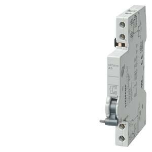
Braking resistors


Обзор
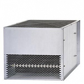
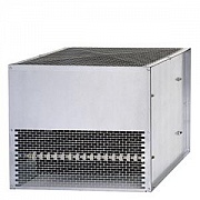
Excess energy in the DC link is dissipated in the braking resistor.
The braking resistor is connected to a Braking Module.
By positioning the braking resistor outside the cabinet or switchgear room, it is possible to extract the heat losses away from the Line Modules/Motor Modules. The level of air conditioning required is therefore reduced.
The maximum permissible cable length between the Braking Module and braking resistor is 100 m.
2 braking resistors with different rated and peak power values are available for the units.
The braking resistor is monitored on the basis of the duty cycle. A temperature switch (NC contact) is also fitted. This responds when the maximum permissible temperature is exceeded and can be evaluated by a controller.
Information about possible load cycles of the braking resistors and other notes are included in the SINAMICS Low Voltage Engineering Manual.